Taconic RF-60TC High-Frequency PCB – DK 6.15 with 10mil, 20mil, 30mil, and 60mil Thickness, Coated with Immersion Gold, Tin, HASL, and OSP
(Printed Circuit Boards are custom-made products, the picture and parameters shown are just for reference)
Experience Superior Performance with Taconic RF-60TC High-Frequency PCBs
Elevate your high-frequency PCB designs with Taconic RF-60TC laminates, engineered for high-power RF and microwave applications. Featuring a ceramic-filled PTFE (Polytetrafluoroethylene) laminate with a fiberglass substrate, RF-60TC delivers a dielectric constant (Dk) of 6.15, ensuring exceptional thermal management, low insertion loss, and enhanced antenna gain.
Designed to operate at lower temperatures and with improved dimensional stability, RF-60TC is perfect for miniaturized antennas, high-power amplifiers, and satellite applications. Its low coefficient of thermal expansion (CTE) and reliable plated through holes (PTH) make it ideal for multilayer PCB designs.
Key Features of Taconic RF-60TC Laminates
1.Advanced Material Composition: Ceramic-filled PTFE with fiberglass substrate for superior performance.
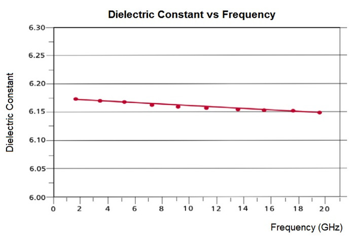
2.Optimized Dielectric Constant (Dk): 6.15 ± 0.15 at 10 GHz, ensuring consistent signal integrity.
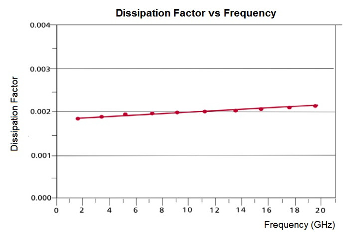
3.Low Dissipation Factor (Df): 0.002 at 10 GHz, minimizing signal loss.
4.High Thermal Conductivity: Exceptional heat dissipation for high-power applications.
5.Low Z-Axis CTE: Ensures reliability in multilayer PCB designs.
6.Low Moisture Absorption: 0.03%, ensuring stability in various environments.
7.Flame Retardant: Meets UL 94 V-0 requirements for safety and compliance.
.jpg)
Why Choose Taconic RF-60TC Laminates?
Improved Loss Tangent: Lower insertion loss and enhanced antenna efficiency.
High Thermal Conductivity: Reduces operating temperatures and extends component life.
Enhanced Dimensional Stability: Ensures reliable performance in multilayer PCBs.
Low Z-Axis CTE: Ideal for reliable plated through holes (PTH).
Excellent Adhesion to Metal: Available in lower profile and heavy metal backing options.
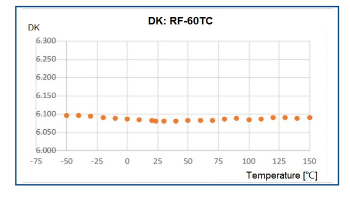
Stable Dk Over Frequency and Temperature: Ensures consistent performance across various conditions.
Applications of Taconic RF-60TC Laminates
High-Power Amplifiers
Miniaturized Antennas (GPS, PATCH, RFID Reader)
Filters, Couplers, and Dividers
Satellite Communications
.jpg)
Our PCB Capability (RF-60TC)
PCB Capability (RF-60TC) |
|
PCB Material: |
PTFE based, ceramic filled fiberglass |
Designation: |
RF-60TC |
Dielectric constant: |
6.15± 0.15 @10 GHz |
Dissipation factor: |
0.002 @10 GHz |
Layer count: |
Single Layer, Double Layer, Multilayer, Hybrid PCB |
Copper weight: |
1oz (35 µm), 2oz (70µm) |
PCB thickness: |
5mil (0.127mm), 10mil (0.254mm); 20mil (0.508mm), 25mil(0.635mm); 30mil (0.762mm), 60mil (1.524mm) |
PCB size: |
≤400mm X 500mm |
Solder mask: |
Green, Black, Blue, Yellow, Red etc. |
Surface finish: |
Bare copper, HASL, ENIG, Immersion silver, Immersion tin, ENEPIG, OSP, Pure gold etc.. |
Upgrade Your High-Frequency PCB Designs with Taconic RF-60TC!
Whether you're working on high-power amplifiers, miniaturized antennas, or satellite communications, Taconic RF-60TC laminates offer the perfect combination of performance, reliability, and thermal management. With low insertion loss, high thermal conductivity, and stable Dk over frequency and temperature, RF-60TC is the ideal choice for your next high-frequency PCB project.
Typical Values of RF-60TC
RF-60TC Typical Values |
|||||
Property |
Test Method |
Unit |
Value |
Unit |
Value |
Dk @ 10 GHz |
IPC-650 2.5.5.5.1 (Modified) |
|
6.15 ± 0.15 |
|
6.15 ± 0.15 |
Df @ 10 GHz |
IPC-650 2.5.5.5.1 (Modified) |
|
0.002 |
|
0.002 |
TcK |
|
ppm/°C |
-3.581 |
ppm/°C |
-3.581 |
Dielectric Breakdown |
IPC-650 2.5.6 |
kV |
55 |
kV |
55 |
Dielectric Strength |
IPC-650 2.5.6.2 |
V/mil |
550 |
V/mm |
21,654 |
Arc Resistance |
IPC-650 2.5.1 |
Seconds |
>180 |
Seconds |
>180 |
Moisture Absorption |
IPC-650 2.6.2.1 |
% |
0.03 |
% |
0.03 |
Flexural Strength (MD) |
IPC-650 2.4.4 |
psi |
10,000 |
N/mm2 |
69 |
Flexural Strength (CD) |
IPC-650 2.4.4 |
psi |
9,000 |
N/mm2 |
62 |
Tensile Strength (MD) |
IPC-650 2.4.19 |
psi |
9,000 |
N/mm2 |
62 |
Tensile Strength (CD) |
IPC-650 2.4.19 |
psi |
7,000 |
N/mm2 |
48 |
Young’s Modulus (MD) |
ASTM D 3039/IPC-TM-650 2.4.19 |
kpsi |
721 |
N/mm2 |
4971 |
Poisson’s Ratio (MD) |
ASTM D 3039/IPC-TM-650 2.4.19 |
|
0.155 |
|
0.155 |
Peel Strength (1 oz. ED) |
IPC-650 2.4.8 |
lbs/in |
8 |
N/mm |
1.43 |
Thermal Conductivity (Unclad) |
IPC-650 2.4.50 |
W/M*K |
0.9 |
W/M*K |
0.9 |
Thermal Conductivity (CH/CH) |
IPC-650 2.4.50 |
W/M*K |
1 |
W/M*K |
1 |
Thermal Conductivity (C1/C1) |
IPC-650 2.4.50 |
W/M*K |
1.05 |
W/M*K |
1.05 |
Dimensional Stability (MD) |
IPC-650 2.4.39 Sec. 5.4 (After Bake) |
mils/in |
0.01 |
mm/M |
0.01 |
Dimensional Stability (CD) |
IPC-650 2.4.39 Sec. 5.4 (After Bake) |
mils/in |
0.69 |
mm/M |
0.69 |
Dimensional Stability (MD) |
IPC-650 2.4.39 Sec. 5.5 (Thermal Stress) |
mils/in |
0.06 |
mm/M |
0.06 |
Dimensional Stability (CD) |
IPC-650 2.4.39 Sec. 5.5 (Thermal Stress) |
mils/in |
0.8 |
mm/M |
0.8 |
Surface Resistivity |
IPC-650 2.5.17.1 (After Humidity) |
Mohm |
1.0 x 10⁸ |
Mohm |
1.0 x 10⁸ |
Volume Resistivity |
IPC-650 2.5.17.1 (After Humidity) |
Mohm/cm |
1.0 x 10⁸ |
Mohm/cm |
1.0 x 10⁸ |
CTE (X, Y axis) |
IPC-650 2.4.41 (RT- 150 °C) |
ppm/°C |
9.9 |
ppm/°C |
9.9 |
CTE (Z axis) |
IPC-650 2.4.41 (RT- 150 °C) |
ppm/°C |
40 |
ppm/°C |
40 |
Density (Specific Gravity) |
IPC-650 2.3.5 |
g/cm3 |
2.84 |
g/cm3 |
2.84 |
Specific Heat |
IPC-650 2.4.50 |
J/gK |
0.94 |
J/gK |
0.94 |
Td (2% Wt. Loss) |
IPC - 650 2.4.24.6 / TGA |
°F |
930 |
°C |
500 |
Td (5% Wt. Loss) |
IPC - 650 2.4.24.6 / TGA |
°F |
960 |
°C |
515 |
Flammability Rating |
UL 94 |
|
V-0 |
|
V-0 |